
Tanks and Hoopers
- By maple scales
- July 17, 2025
- Accecories
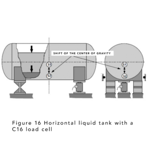
6.3 Horizontal tanks for liquids
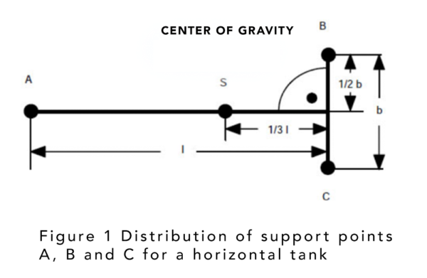
Horizontal liquid tanks generally meet the condition that the centre of gravity of the contents moves approximately along a vertical line as they are filled or emptied of material.
A setup with a load cell under one tank support and two fixed couplings under the other tank support is therefore sufficient for relatively simple level measurements.
An ideal tank supports half of its weight on a self-centring pendulum load cell and the other half on two fixed couplings. Under normal circumstances no further clamping elements are needed. However, on very long tanks, fixed stops can be fitted as additional protection against tipping in the event of lateral impacts against the tank, to limit lateral movements on either side of the tank base supported by the load cell.
In practical applications, the symmetrical distribution of the contents is often disturbed by a slight and deliberate tilt of the tank base to one side, and also by the outlet pipe which is placed on the same side. A self-centring arrangement of three load cells is the optimal solution for more accurate weighing, and fixed stops are the best way to ensure horizontal holding.
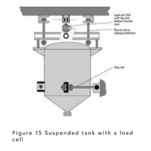
6.2.2 Central suspension on a single load cell
With this arrangement, special support is essential to prevent oscillations and overturning.
6.2 Suspended tanks
Problems with the centring of suspended tanks can be eliminated or mitigated with simple round flexible braces.
In addition to the anti-tilt protection, which is always necessary, tensioners are also required to prevent oscillations and twists.
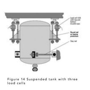
6.2.1 Suspension on two or three load cells
The simplest design requires several tangentially placed stays. In cases where tensions are low, a lower side outlet pipe can perform the same function as the stays.
In addition to the anti-tilt protection, which is always necessary, tensioners are also required to prevent oscillations and twists.
6.2.1 Suspension on two or three load cells
The simplest design requires several tangentially placed stays. In cases where tensions are low, a lower side outlet pipe can perform the same function as the stays.
6. Examples of load cell designs and installations
Examples of typical tank designs are presented in schematic form below. Design details and references to problems are presented in more detail in the specific sections.
6.1 Vertical tanks
Installations with two fixed supports and one load cell are suitable for tanks with centrally filled liquids and bulk materials. The tank should have a symmetrical design so that the line representing the center of gravity at different fill levels forms approximately a vertical line, appropriate for the required accuracy.
In all other cases—especially when higher accuracy is needed—it is preferable to use an installation with three load cells, or even more in some cases.
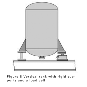
6.1.1 Rigid installation of a load cell
This simple design with one support and a rigidly mounted load cell is not recommended, as it leads to adverse effects on the load cell. Due to deformations that occur as the fill level changes, as well as vibrations and temperature fluctuations, it is generally not possible to avoid negative impacts on the load cells.
Nevertheless, there are some examples of this design in use.
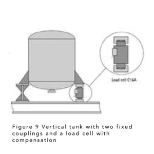
6.1.2 Vertical tank with two fixed supports and a load cell with compensation This form of level measurement consists of a
load cell placed in a cradle with two fixed supports, which also serve to contain the horizontal movement of the tank. This design economically avoids undesirable effects on the load cell.
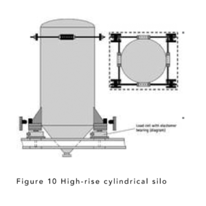
6.1.3 Cylindrical silo on three or four load cells
Normally, three load cells allow level measurement with good accuracy. However, four load cells are sometimes used, for example in symmetrical rectangular tanks. This arrangement is generally unfavourable from a static point of view and has a Higher cost. The cells are easily installed in the structure. Elastomer couplings are self-centering and do not require tie rods. They are usually combined with fixed stops. For very high tanks, additional tie rods are required at the
top. The example shows a design with tie rods without initial tension, blocked at one end. The fixed stops continually touch the tank when it moves slightly out of its ideal position, which is unavoidable. Contact friction leads to force derivations. Other less frequent alternatives are roller brakes and cable guides.
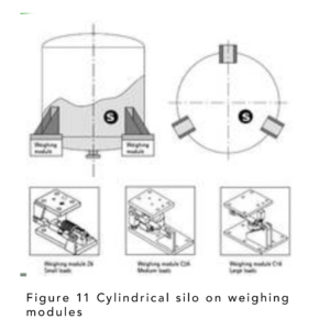
6.1.4 Cylindrical silo on three weighing modules
The use of three weighing modules with integrated tension elements that contact the circumference of the structure tangentially keeps the tank horizontally stable without the need for additional measures. The anti-tip device, also integrated into the weighing module, prevents the tank from tilting or rocking.
This eliminates the need for several external structural components. Typical weighing modules for low, medium, and high mounting heights are also illustrated as examples. These standardized elements simplify the design and lead to significant cost savings in construction.
On the other hand, the design requires great care and specific expenses to ensure that the contact surfaces are parallel, the heights are aligned, and so on.
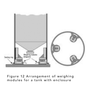
6.1.5 Tanks with casing over weighing modules
Shell tanks, which are frequently used in practical applications, have an outer shell that extends to the base and serves to ensure the overall stability of the design. It is not easy to accommodate such installations on load cells. Figure 12 shows a layout for weighing such tanks with load cells. This layout is also relatively easy to install in existing systems.
Stands are mounted or welded on the inside of the tank wall. The load is applied rigidly to the load cell.
Weighing modules are preferable in this case, since they contain an anti-tilt device, etc. (not shown in Figure 12 for clarity). A slight elevation of the structure is sufficient to transfer the full weight to the load cells. The base of the shell must often be sealed. For this purpose, a circular sealing gasket can be used, which, due to its flexibility, does not cause force deviations.
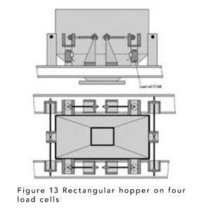
6.1.6 Rectangular hopper on four load cells at filling stations
The conditions at filling stations are very tough, due to vibrations from the conveying systems, oscillations of the connected supply and emptying equipment and, if the weighing hopper is part of a mobile system, also due to acceleration during transfers.
When heavy materials are introduced into the tank, they can hit the inclined surfaces with sufficient force to
cause considerable shear loads. In such cases, a particularly stable clamping system with a high initial tension must be included. Sometimes the tank is clamped with an additional
fixture, which is only released during the weighing process.
In this case, rectangular symmetry is advantageous for reasons of stability and is therefore usually
included in the load cell arrangement. Load cells with elastomer and pendulum couplings are used (as in the example).
6.1 Vertical tanks
Installations with two fixed supports and one load cell are suitable for tanks with centrally filled liquids and bulk materials. The tank should have a symmetrical design so that the line representing the center of gravity at different fill levels forms approximately a vertical line, appropriate for the required accuracy.
In all other cases—especially when higher accuracy is needed—it is preferable to use an installation with three load cells, or even more in some cases.
6.1.1 Rigid installation of a load cell
This simple design with one support and a rigidly mounted load cell is not recommended, as it leads to adverse effects on the load cell. Due to deformations that occur as the fill level changes, as well as vibrations and temperature fluctuations, it is generally not possible to avoid negative impacts on the load cells.
Nevertheless, there are some examples of this design in use.
6.1.2 Vertical tank with two fixed supports and a load cell with compensation This form of level measurement consists of a
load cell placed in a cradle with two fixed supports, which also serve to contain the horizontal movement of the tank. This design economically avoids undesirable effects on the load cell.
6.1.3 Cylindrical silo on three or four load cells
Normally, three load cells allow level measurement with good accuracy. However, four load cells are sometimes used, for example in symmetrical rectangular tanks. This arrangement is generally unfavourable from a static point of view and has a Higher cost. The cells are easily installed in the structure. Elastomer couplings are self-centering and do not require tie rods. They are usually combined with fixed stops. For very high tanks, additional tie rods are required at the
top. The example shows a design with tie rods without initial tension, blocked at one end. The fixed stops continually touch the tank when it moves slightly out of its ideal position, which is unavoidable. Contact friction leads to force derivations. Other less frequent alternatives are roller brakes and cable guides.
6.1.4 Cylindrical silo on three weighing modules
The use of three weighing modules with integrated tension elements that contact the circumference of the structure tangentially keeps the tank horizontally stable without the need for additional measures. The anti-tip device, also integrated into the weighing module, prevents the tank from tilting or rocking.
This eliminates the need for several external structural components. Typical weighing modules for low, medium, and high mounting heights are also illustrated as examples. These standardized elements simplify the design and lead to significant cost savings in construction.
On the other hand, the design requires great care and specific expenses to ensure that the contact surfaces are parallel, the heights are aligned, and so on.
6.1.5 Tanks with casing over weighing modules
Shell tanks, which are frequently used in practical applications, have an outer shell that extends to the base and serves to ensure the overall stability of the design. It is not easy to accommodate such installations on load cells. Figure 12 shows a layout for weighing such tanks with load cells. This layout is also relatively easy to install in existing systems.
Stands are mounted or welded on the inside of the tank wall. The load is applied rigidly to the load cell.
Weighing modules are preferable in this case, since they contain an anti-tilt device, etc. (not shown in Figure 12 for clarity). A slight elevation of the structure is sufficient to transfer the full weight to the load cells. The base of the shell must often be sealed. For this purpose, a circular sealing gasket can be used, which, due to its flexibility, does not cause force deviations.
6.1.6 Rectangular hopper on four load cells at filling stations
The conditions at filling stations are very tough, due to vibrations from the conveying systems, oscillations of the connected supply and emptying equipment and, if the weighing hopper is part of a mobile system, also due to acceleration during transfers.
When heavy materials are introduced into the tank, they can hit the inclined surfaces with sufficient force to
cause considerable shear loads. In such cases, a particularly stable clamping system with a high initial tension must be included. Sometimes the tank is clamped with an additional
fixture, which is only released during the weighing process.
In this case, rectangular symmetry is advantageous for reasons of stability and is therefore usually
included in the load cell arrangement. Load cells with elastomer and pendulum couplings are used (as in the example).
5. Pressure tanks
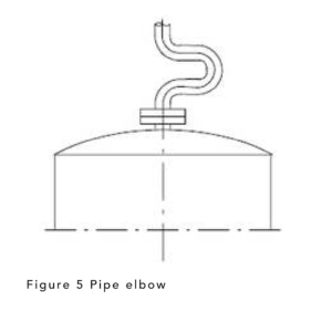
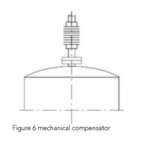
In closed plants, the system pressure can affect the weighing results. In the chemical industry, high positive pressures are required for some processes. Extraction plants where powdered material is weighed, on the other hand, operate with negative pressures of 100-300 mbar. If the pipe is connected to the tank vertically, as shown in Figures 5 and 6, a force is exerted that directly affects the measurement results. The effect is equal to the product of the force and the pipe section. If the pressure conditions remain constant during the weighing process, this quantity can be taken into account (calculated) in the measurement. In any case, a horizontal pipe layout is preferable and more appropriate than a vertical connection. In this case, the supports of the installation absorb the parasitic forces that arise.
4. Supply connections on the tanks
Tanks often require supply connections, for example for loading and unloading material or for the electrical, hydraulic or pneumatic supply of additional units mounted on the tank.
These supply connections can cause force shunts, which result in errors affecting the measurement accuracy of the weighing device. Supply connections
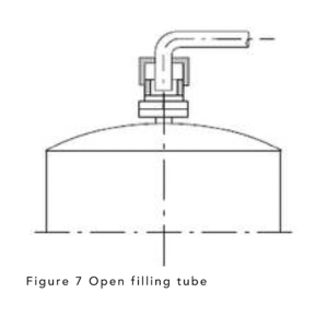
should be flexible in the vertical direction. Figures 3 to 7 show some examples of suitable designs for supply connections. In any case, for economic reasons these aspects should always be taken into account during the design and planning phase.
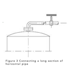
If rigid pipes without flexible connections are used, it is preferable to connect the tank with a horizontal pipe section that is as long as possible. This pipe section should be provided with some element that compensates for the expansion in the longitudinal direction (Figure 3). The horizontal section of pipe has a spring effect in the vertical direction, the greater the horizontal length, the less so. The mechanical force exerted by the pipe in the form of pseudoload (tension or compression) on the load cells is proportionally reduced, until it is no longer significant for measurement accuracy.
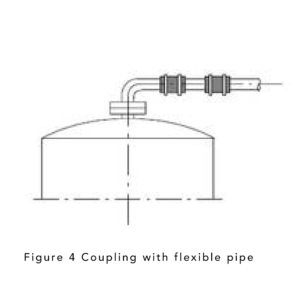
Instead of a single long section of pipe, several flexible couplings can be used (Figure 4). The use of hose connections made of elastic and easily malleable materials gives good results and prevents force transfers. Of course, in this case, the compatibility of elastic materials with the product and with cleaning materials (e.g. in the food or pharmaceutical industry) must be checked.
These supply connections can cause force shunts, which result in errors affecting the measurement accuracy of the weighing device. Supply connections
should be flexible in the vertical direction. Figures 3 to 7 show some examples of suitable designs for supply connections. In any case, for economic reasons these aspects should always be taken into account during the design and planning phase.
If rigid pipes without flexible connections are used, it is preferable to connect the tank with a horizontal pipe section that is as long as possible. This pipe section should be provided with some element that compensates for the expansion in the longitudinal direction (Figure 3). The horizontal section of pipe has a spring effect in the vertical direction, the greater the horizontal length, the less so. The mechanical force exerted by the pipe in the form of pseudoload (tension or compression) on the load cells is proportionally reduced, until it is no longer significant for measurement accuracy.
Instead of a single long section of pipe, several flexible couplings can be used (Figure 4). The use of hose connections made of elastic and easily malleable materials gives good results and prevents force transfers. Of course, in this case, the compatibility of elastic materials with the product and with cleaning materials (e.g. in the food or pharmaceutical industry) must be checked.
3. Centre of gravity of a tank
In theory, the center of gravity of a filled tank should not be higher than the tank's support points, but this condition is often not met.
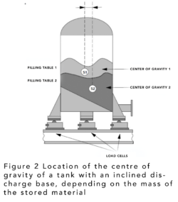
For reasons of stability, it is desirable for the center of gravity to be below the support points. The position of the center of gravity in relation to the fill level has a significant effect on the number of load cells to be used. If filling is carried out symmetrically to the load cells, a weighing device consisting of a single load cell is possible, because the position of the center of gravity shifts along a vertical line (see also 6.3). However, if the center of gravity also shifts laterally during the filling or emptying process, then all supports must be equipped with load cells. In this type of application, fixed or tilting couplings should not be used.
Figure 2 shows the need to install load cells at all support points if the position of the center of gravity changes.
Structural design of tank weighing systems
1. Basic principles
When installing load cells in tanks, a few essential rules must be followed. For example, tanks are
often subject to weathering or production-related effects. When
vertical tanks are built outdoors (silos, coal hoppers, etc.), the relevant building regulations applicable to the structures must be observed. In this respect, retrofitting weighing equipment
can be considered a “significant change” for the purposes of the regulations. In such cases, it is recommended to
seek advice from a structural engineer. In general, building regulations specify that
safety elements must be “state-of-the-art.” For example, Part 4 of the German standard DIN 1055
“Load assumptions for structural components” deals with wind loads.
The designer of a tank or reservoir must also be aware of any specific internal company regulations. Tanks often need to be secured so that they cannot be moved, even if they are
under a roof, if their contents are hazardous, and if forklifts are working in the vicinity of the storage area.
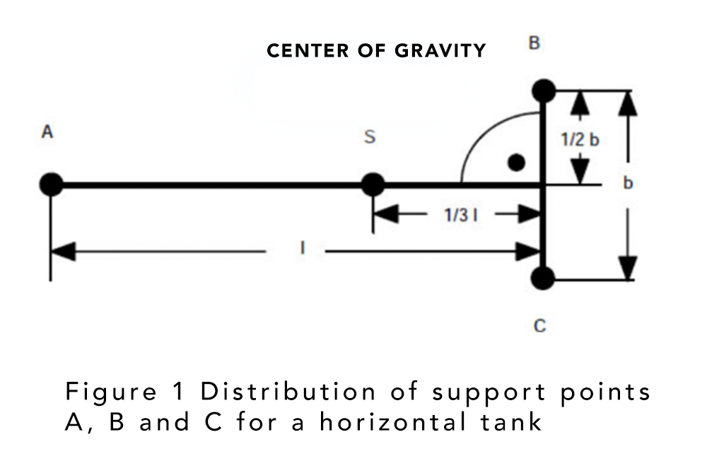
2. Load distribution
When the tank is placed on three support points and a load cell is placed on each support,
an optimal distribution of load cells is achieved for determining the weight of the tank. This condition is
known as isostatic. The total load must be distributed as evenly as possible between the three load cells.
In the case of vertical or suspended cylindrical tanks, the best way to meet this requirement
is to place the three cells at the same distance from the vertical axis of the tank, with a separation of 120°
from each other in the same plane.
Figure 1 shows the distribution of support points for horizontal tanks.
If load cells are not installed on all supports, it is recommended to distribute the load unevenly.
Supports with load cells must be subjected to higher loads than supports without load cells. This arrangement improves the overall accuracy of the weighing system. When designing the system and selecting the
load cells, it is preferable that all load cells be subjected to loads of the same magnitude.
If a tank has four or more support points, it is considered to be statically unstable. In such cases, load cells must be installed at all support points. During assembly, an even distribution of the load on the individual transducers must be achieved. To achieve this, the loads on the transducers must be measured individually. If there are unacceptable differences, the height of the load cells affected must be changed (with shims, etc.). In general, load cells located at a low height are placed diagonally opposite each other.